
Hooking Up External Drivers to the CNC xPRO V3
Posted by Mike on 23rd Apr 2018
With the release of the xPRO V3, solder points were added to aid in hooking up external driver. In this post we will cover how to wire external stepper motor drivers to the CNC xPRO V3. For our demonstration purpose we will be using the DQ542MA stepper motor drivers. Let's gather up some some supplies!
Tools Needed:
Wire Strippers/cutters
Soldering Iron
Small flat head screw driver
Supplies Needed:
Solder
Hookup wire - Recommend: 16awg red and black, 22awg blue, green, yellow
External Drivers
Get to Wiring
For those not interested in reading the fine print, here are some picture (fine print to follow)
First up, location of and labeling for the solder points to add external drivers

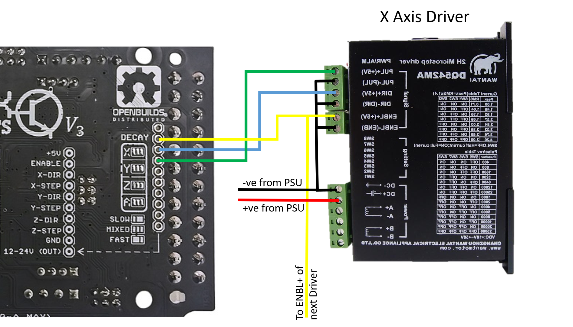
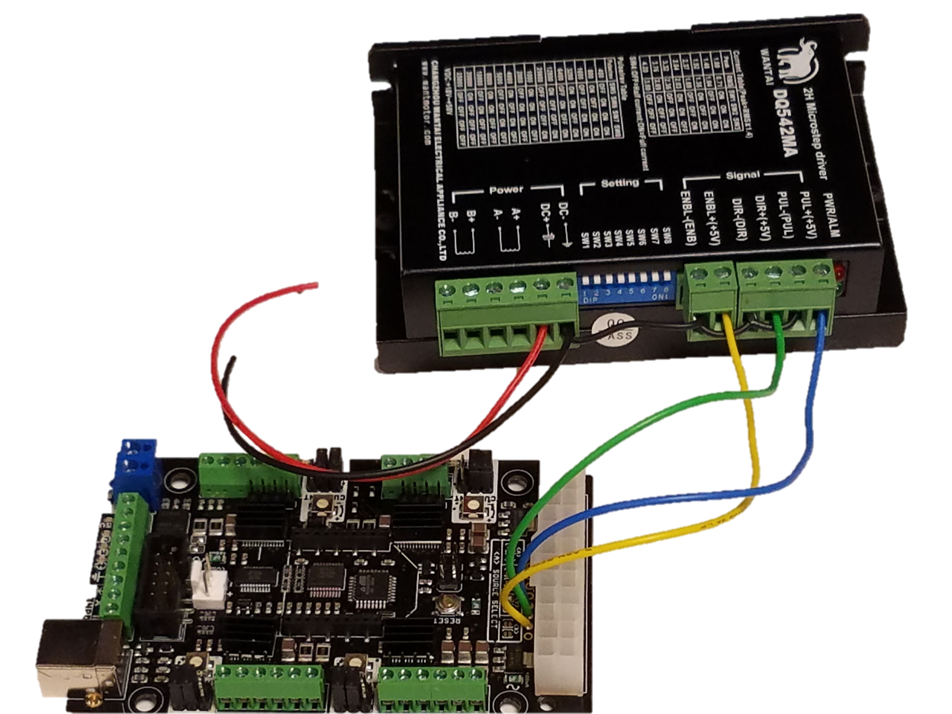
Next, connecting the X axis and enable signals to the first DQ542MA driver (note: DQ542MA mirrored to avoid ratsnest of wiring diagram)
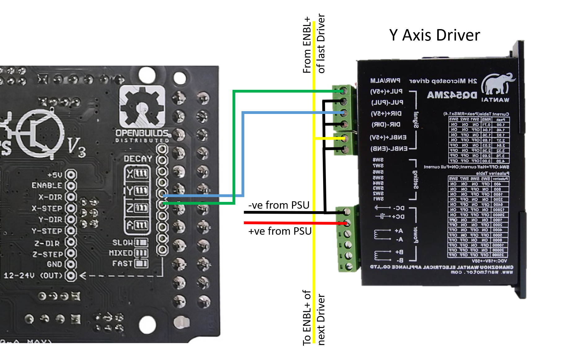
Now, connecting the Y axis signals and daisy chaining the enable signal
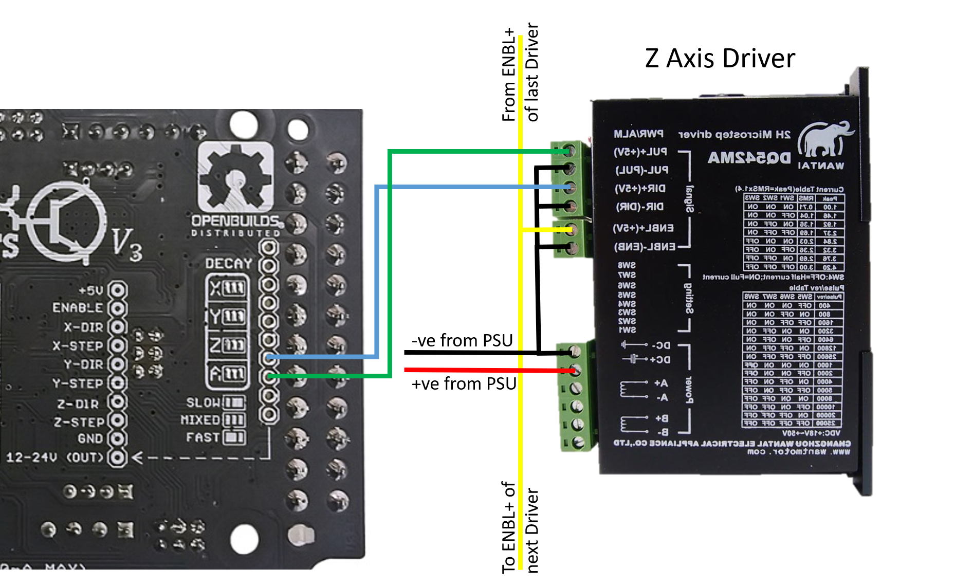
Lastly, connect the Z axis driver and daisy chain the enable signal
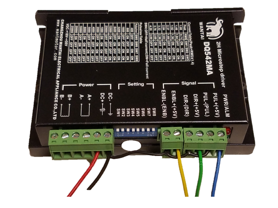
At the end each axis should look something like this (X shown for reference)
***Note, each signal on the DQ542MA needs a negative reference for the isolation circuitry
Fine Print Below
Roughly define final placement of: PSU, xPRO, and External drivers. Do not cross AC power and USB connection. Measure wire length from PSU to external drivers, measure wire length from xPRO to external drivers.
Optional (but recommended): Define color code for wiring – here we will use:
Red – positive power
Black – negative power
Blue – Step signals (there will be 3 Blue wires)
Green – Direction signals (there will be 3 White wires)
Yellow – Enable Signals
Cut (1) Blue and (1) Green wire to run from the xPRO to each external driver. Cut (1) Yellow wire to run from the xPRO to the closest external driver, and (1) Yellow wire to hop between each external driver. Strip roughly ¼” of each end.
Solder one end of the green wires into the x,y, and z-dir solder point, solder one end of the blue wires into the x, y and z-step solder point. Tape or zip tie the wires corresponding to each axis together (i.e tape x-step and x-dir)
Solder one yellow wire to the ENABLE solder point.
For each axis - wire end of green wire to external driver ‘Dir+(+5V)’ input, wire end of blue wire to external driver ‘PUL+(+5V)’ input.
Wire end of yellow wire to the closest external driver ‘ENBL+(+5V)’ input.
Daisy chain remainder of yellow wires to other external driver ‘ENBL+(+5V)’ inputs (picture)
****DOUBLE CHECK POWER SUPPLY IS OFF****
Ensure your external drivers are rated for your power supply voltage. Note: The xPRO is rated for a maximum voltage of 24V – applying voltage above this will release the magic smoke
Run one red wire from the positive power rail to each external driver ‘DC+’ power input.
Run one black wire from the negative (DC negative NOT the AC ground) of the power supply to each external driver ‘DC-’ power input.
Cut 3 short black wires for each external driver. These will be used to supply the negative logic.
Daisychain ‘DC-‘ to ‘ENBL-‘, ‘Dir-‘, and ‘PUL-‘ on each external driver
Check documentation on stepper motors, and wire up the A and B coils
Get moving!
*** NOTES:
- Wire ‘ENBL+(+5V)’ to a 5V source and the motors will always be energized
- Don’t forget to set your current and pulse/revolution using the green dip switches on the front of the driver